
Source: Four Point Probes
The Measurement of Sheet Resistivity
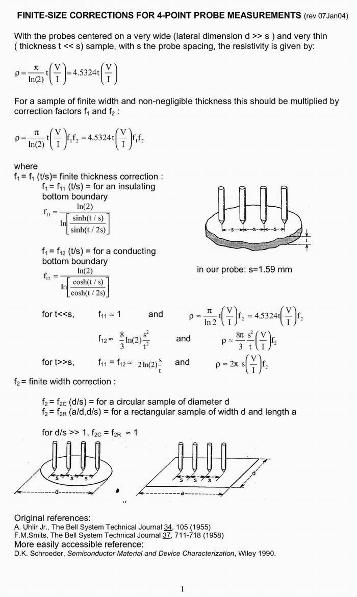
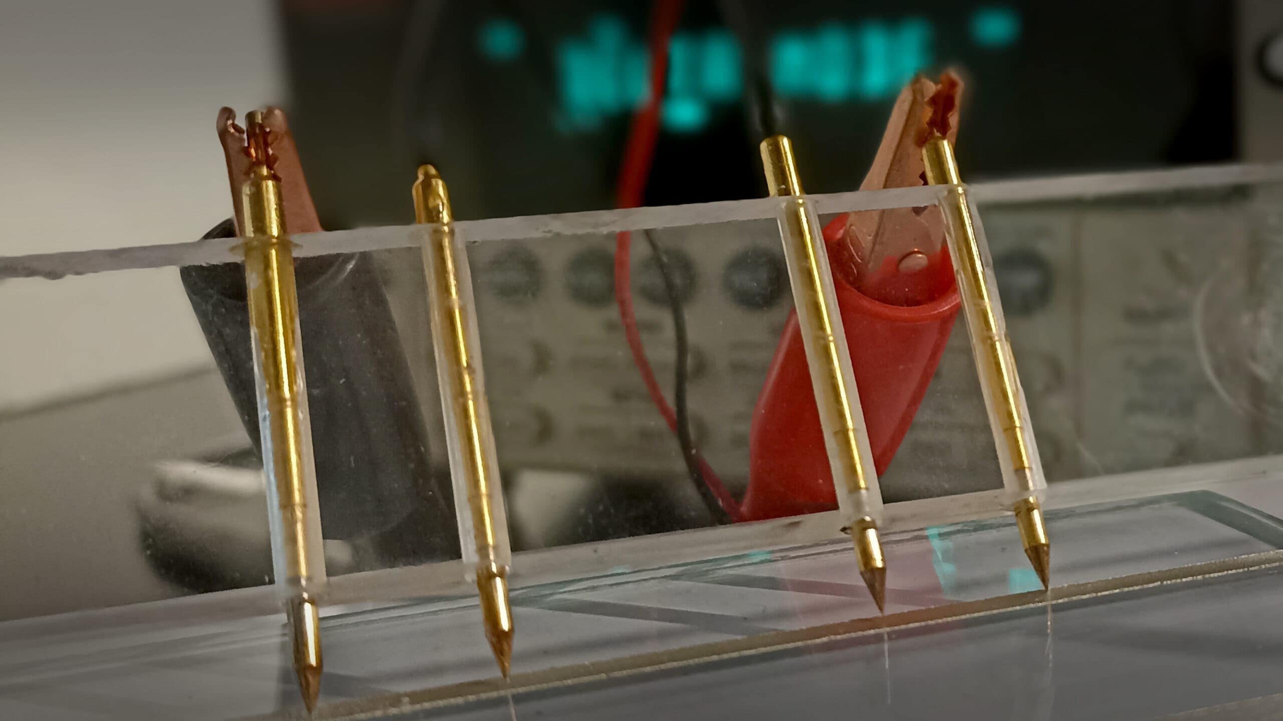
Sheet resistivity of the top emitter layer can be easily measured using a four-point probe. A current is passed through the outer probes, inducing a voltage in the inner voltage probes. The junction between the n and p-type materials acts as an insulating layer, requiring the cell to be kept in the dark.
The emitter sheet resistivity of silicon solar cells typically falls within the range of 30-100 Ω/□. In practice, a current of 4.53 mA is used, making the resistivity equivalent to the voltage reading in mV.
The Measurement of Bulk Resistivity
Measuring bulk resistivity is similar to sheet resistivity measurement, but reports resistivity in Ω-cm using the wafer thickness, t:
ρ = 4.532 * V / I * t
Where t represents the layer or wafer thickness in cm. For wafer thickness less than half the probe spacing (t < s/2), the formula simplifies. For thicker samples, the formula adjusts based on the probe spacing, s.
Measurement Problems
While the four-point probe method is straightforward, there are experimental considerations to address. Applying metal to a semiconductor creates a Schottky diode rather than an ohmic contact. Very high or low resistivity samples may require adjusting the drive current for accurate readings. Samples with cut or lapped surfaces are easier to measure than those with polished surfaces.
High Resistivity Samples
For high resistivity samples, reducing the current prevents excessively high voltages at the contacts. It’s advisable to keep the voltage on the inner probes below 100 mV/mm.
Low Resistivity Samples
Low resistivity samples, with ohmic contacts to silicon, are typically easier to measure. For very low resistivity, increasing the current to 45.3 mA and adjusting the voltmeter scale may be necessary. However, very low resistivity samples may experience resistive heating due to the current passing through, impacting the measured resistivity.
Source: MG Chemicals