
Source: MDPI
Calculating Solar Position for Solar Modules
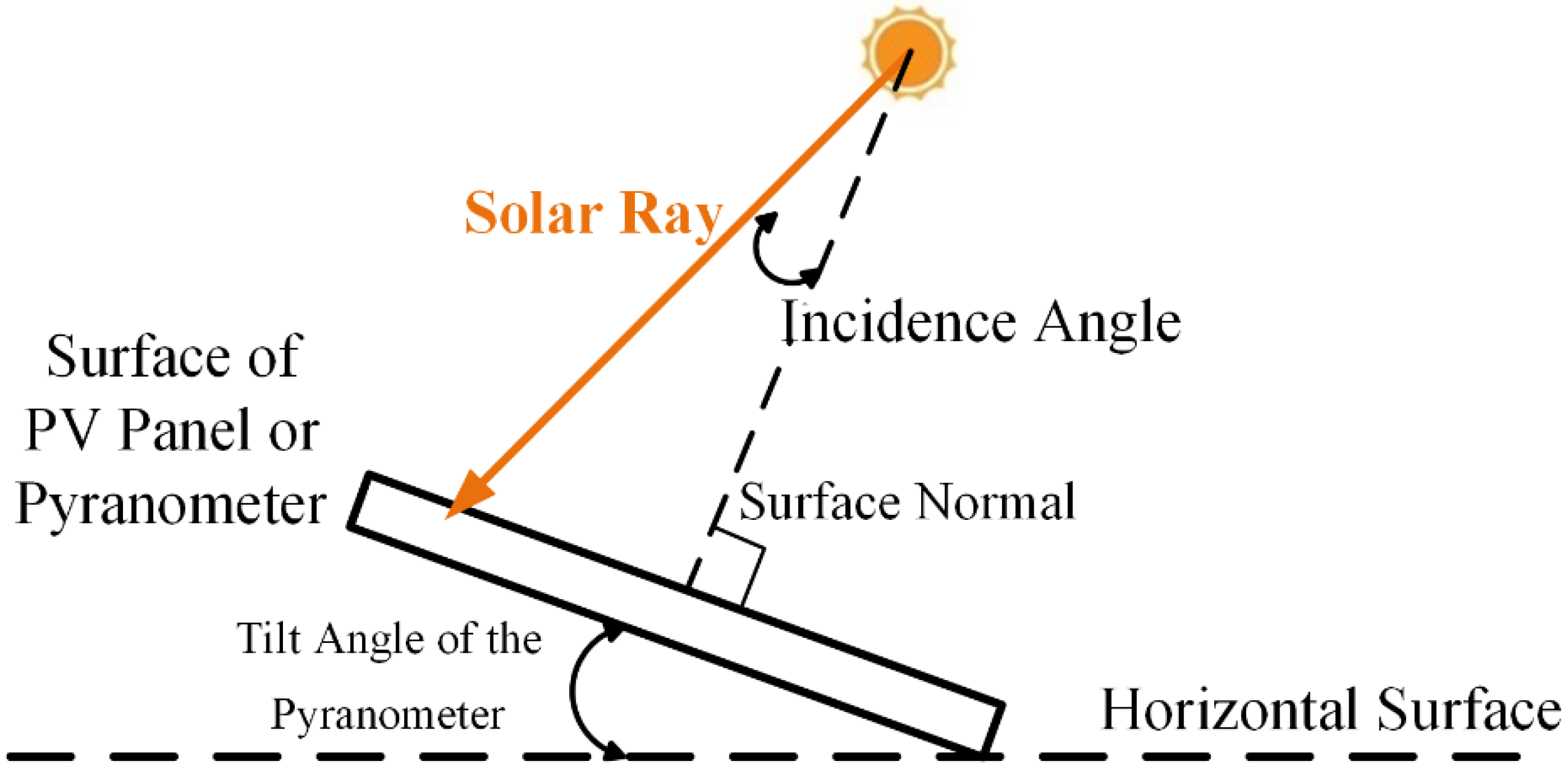
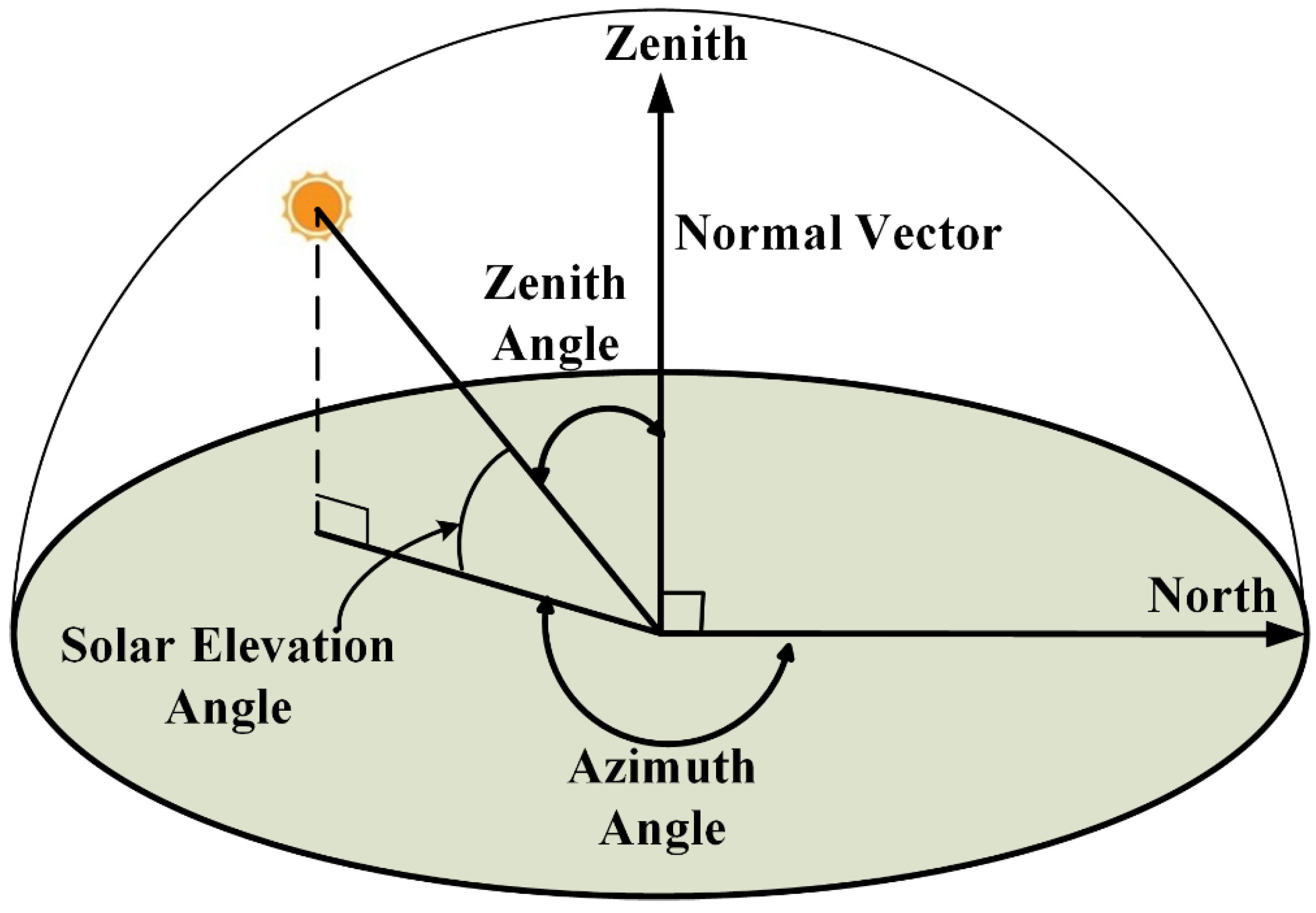
When determining the optimal tilt and orientation of solar modules, various angles come into play. These angles include the sun elevation angle (α), sun azimuth angle (Θ), module tilt angle (β), and azimuth angle that the module faces (Ψ). Understanding these angles is crucial for maximizing the efficiency of solar energy capture.
Module Tilt and Orientation
The module tilt angle (β) refers to the angle at which the module is positioned relative to the ground. A module lying flat on the ground has a tilt angle of 0°, while a vertical module has a tilt angle of 90°. The azimuth angle (Ψ) indicates the direction the module faces, with most modules aligned to face the equator. In the southern hemisphere, modules typically face north (Ψ = 0°), while in the northern hemisphere, they face south (Ψ = 180°).
Calculating Light Intensity on Modules
Calculating the intensity of light incident on a module involves considering the sun’s position, the Airmass formula, and the module’s tilt and orientation angles. The intensity of light on a module is influenced by factors such as the sun’s azimuth and elevation angles, as well as the Airmass units.
Using Vectors for Solar Direction Calculation
As the tilt and orientation of solar modules become more complex, using vectors can simplify the calculation of solar direction. By converting solar directions of azimuth and elevation to vectors, determining the reduction in light intensity on tilted surfaces becomes more straightforward. The reduction in intensity can be calculated using the dot product between the incident ray and the normal to the module.
Source: MDPI
Feel free to comment your thoughts.